About the Project
Modular FPGA-based electronics for the ASTRI camera, enabling high-speed SiPM readout, real-time triggering, and autonomous calibration in Cherenkov telescopes.
-
Date
July 2024
Nuclear Instruments
Caen
Eie Group
WeeRoc
INAF - Istituto Nazionale di Astrofisica
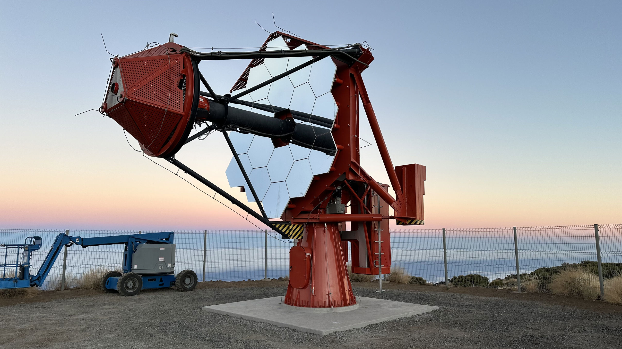
The ASTRI Camera, developed within the framework of the Cherenkov Telescope Array (CTA), features a highly modular, FPGA-centric readout and control system designed to support fast, low-noise photon detection using Silicon Photomultipliers (SiPMs). Installed on a novel dual-mirror Schwarzschild–Couder telescope, ASTRI’s camera electronics process data from 37 Photon Detection Modules (PDMs), enabling precise event timestamping, calibration, and environmental monitoring under real observing conditions. The design emphasizes real-time processing, robustness, and seamless integration with observatory-level infrastructure.
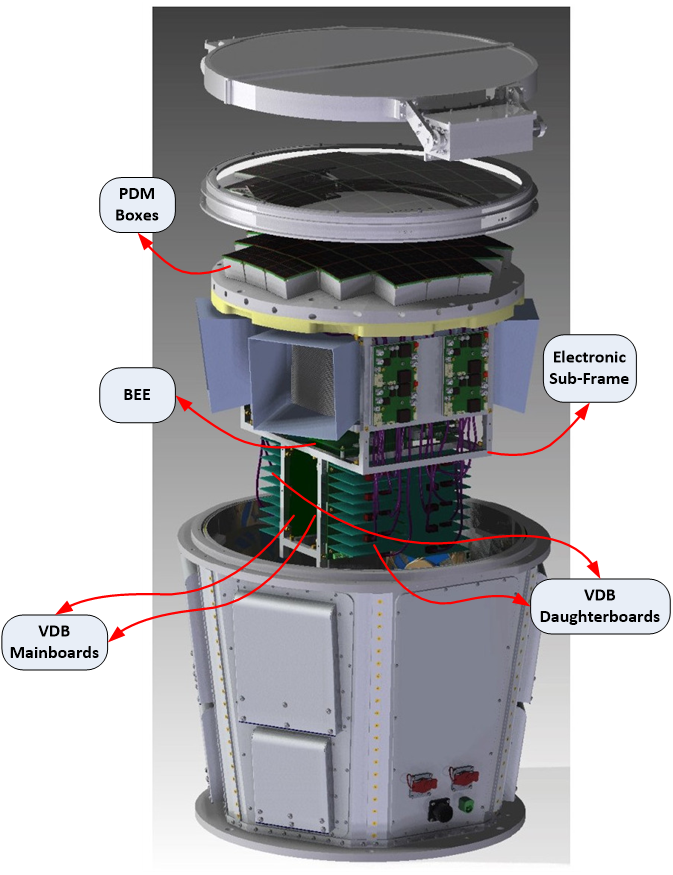
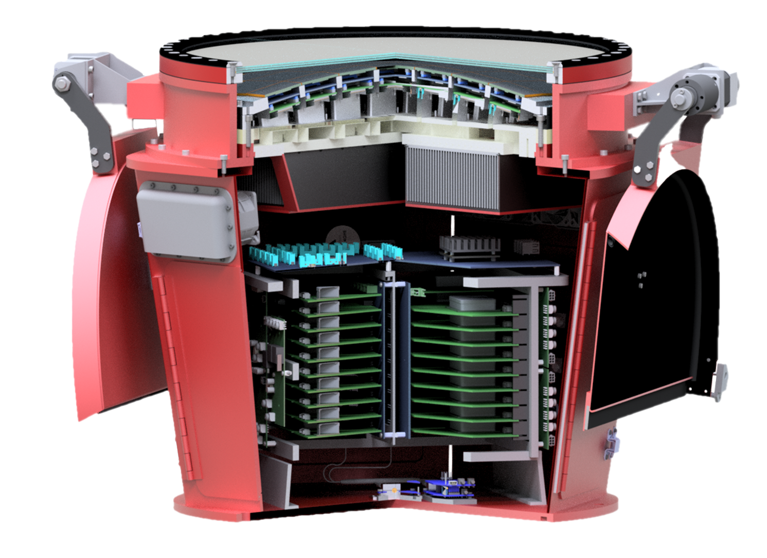
Complete assembly of the ASTRI camera, highlighting all major electronic subsystems: PDMs, BEE, VDBs, TEC modules, lid actuators, and the calibration laser.
Complete assembly of the ASTRI camera, highlighting all major electronic subsystems: PDMs, BEE, VDBs, TEC modules, lid actuators, and the calibration laser.
Photon Detection Module (PDM) assembly showing the SiPM sensor array, CITIROC ASIC-based front-end board, and integrated FPGA for signal processing.
Photon Detection Module (PDM) assembly showing the SiPM sensor array, CITIROC ASIC-based front-end board, and integrated FPGA for signal processing.
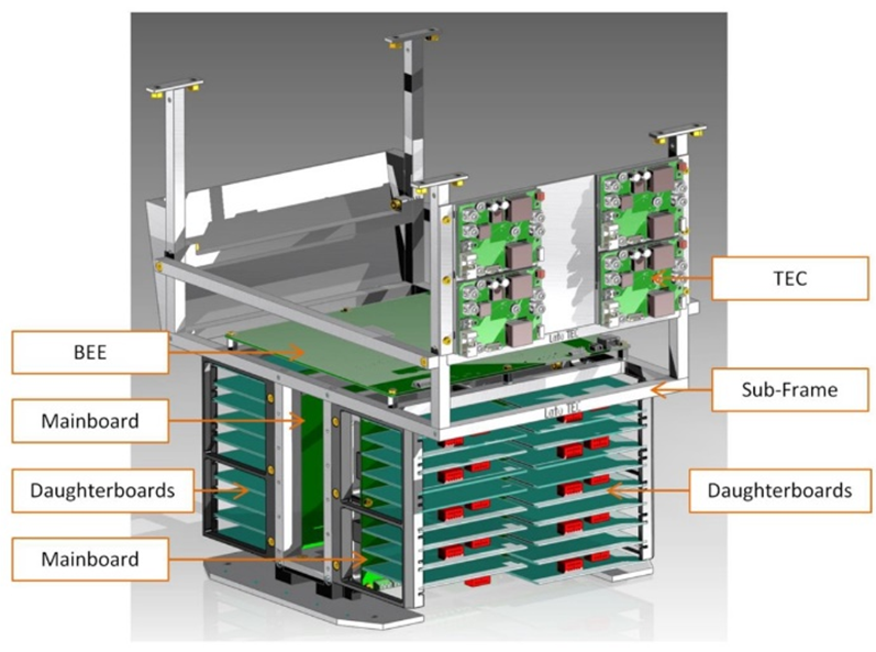
ASTRI camera electronics rack including the Back-End Electronics (BEE), Voltage Distribution Boxes (VDBs), thermomechanical systems (TEC and LID), and optical calibration laser.
ASTRI camera electronics rack including the Back-End Electronics (BEE), Voltage Distribution Boxes (VDBs), thermomechanical systems (TEC and LID), and optical calibration laser.
Our Contribution: Electronics, firmware and software design
Nuclear Instruments has led the design and implementation of the entire electronic system of the ASTRI camera, from concept to deployment. Our contributions include:
- Custom-designed PDM electronics with SiPM front-end, CITIROC ASIC integration, and FPGA-based real-time processing
- Back-End Electronics (BEE) featuring three dedicated FPGAs for Acquisition, Trigger, and Control tasks
- Voltage Distribution Boxes (VDB) and High-Voltage modules uniquely engineered to support continuous 100 mA operation with <1 mV ripple and exceptional thermal stability
- Complete firmware suite for all FPGAs, including real-time acquisition on PDMs, trigger and DAQ firmware on the BEE, and embedded control on VDB and HV systems
- Camera software infrastructure running on the Zynq platform, managing scientific data acquisition, configuration, calibration routines, and all slow control functionalities
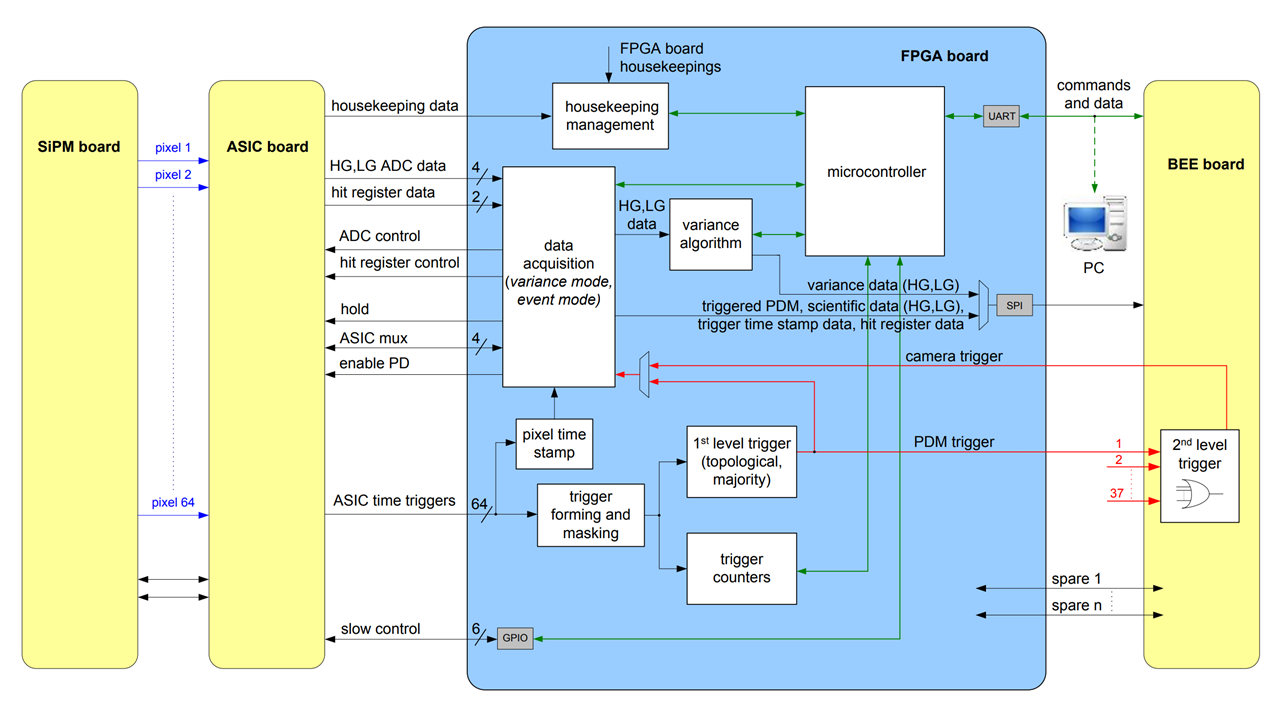
PDM – Front-End Electronics and Detector
At the core of the ASTRI camera are 37 Photon Detection Modules (PDMs). Each PDM includes:
- A 64-pixel SiPM array
- A Front-End Electronics (FEE) board with CITIROC ASICs for analog signal processing
- A dedicated FPGA board for digital control, triggering, and data buffering
The CITIROC ASICs (developed by Weeroc) provide dual-gain shaping for extended dynamic range and peak-hold functionality. The FEE FPGA processes the analog signals, applying topological and majority-based triggering. It also manages real-time acquisition, calculates signal variance, and interacts with a high-resolution Time-to-Digital Converter (TDC) for precise timestamping of Cherenkov pulses. These features enable accurate 3D reconstruction of the air-shower geometry from the recorded light fronts.
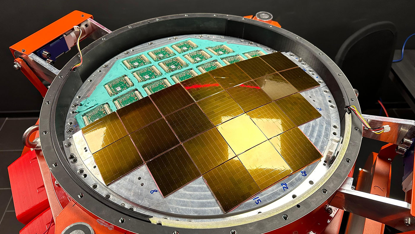
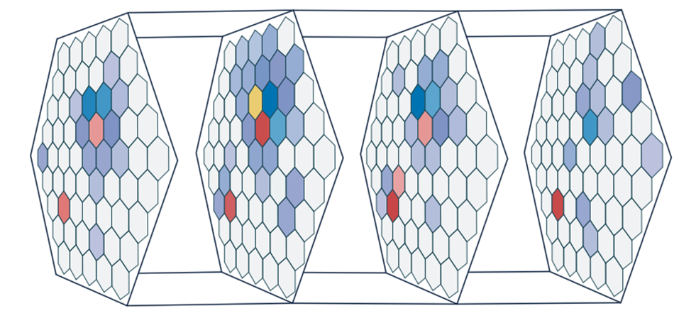
View of the ASTRI focal plane with multiple Photon Detection Modules (PDMs) inserted and partially mounted SiPM arrays.
View of the ASTRI focal plane with multiple Photon Detection Modules (PDMs) inserted and partially mounted SiPM arrays.
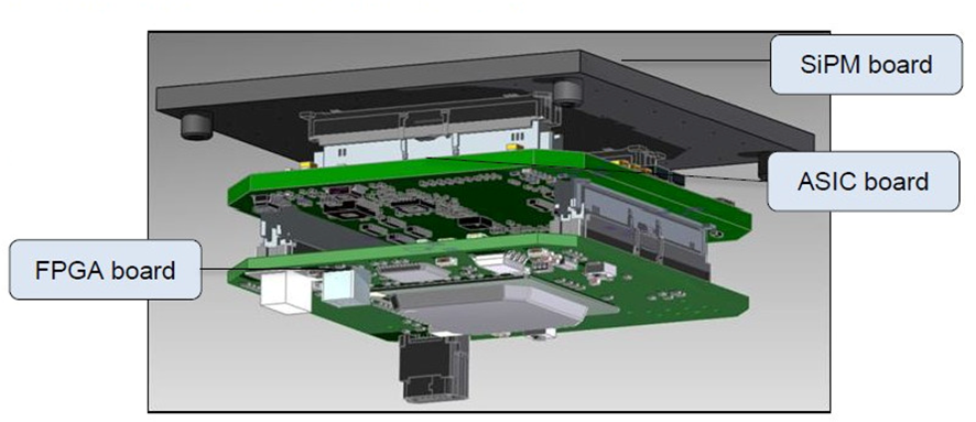
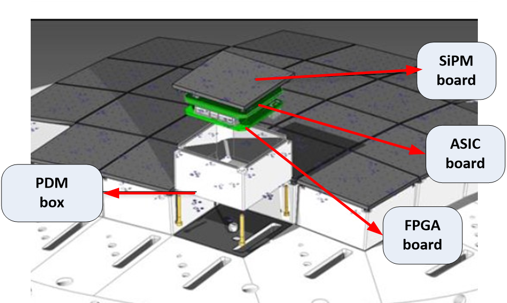
Exploded view of a Photon Detection Module (PDM) showing the stacked architecture of the SiPM board, CITIROC ASIC front-end, and FPGA processing board.
Exploded view of a Photon Detection Module (PDM) showing the stacked architecture of the SiPM board, CITIROC ASIC front-end, and FPGA processing board.
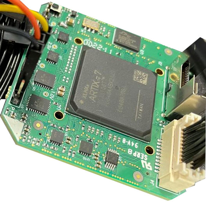
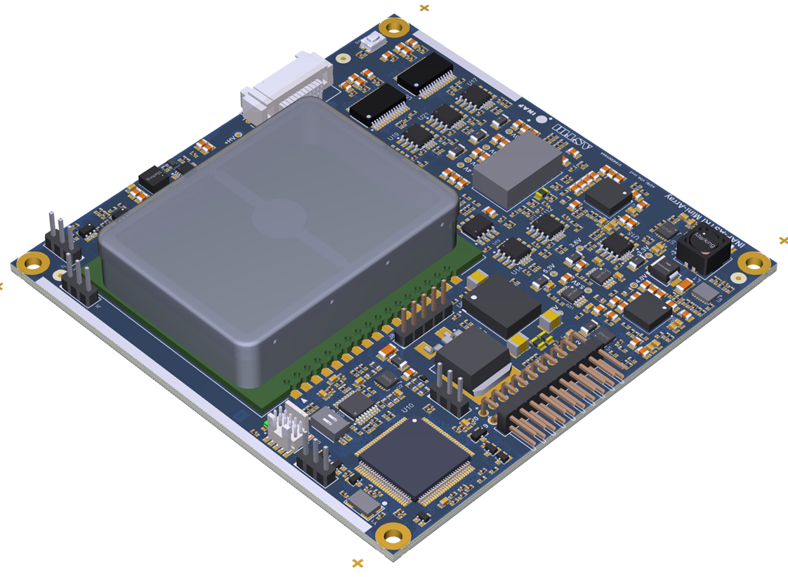
Close-up of the FPGA board used in the ASTRI Front-End Electronics, responsible for real-time triggering, data buffering, and TDC timestamping.
Close-up of the FPGA board used in the ASTRI Front-End Electronics, responsible for real-time triggering, data buffering, and TDC timestamping.
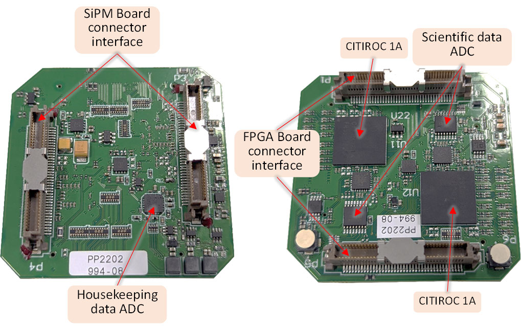
Detail of the CITIROC-based ASIC board handling analog signal shaping, dual-gain processing, and peak detection for each SiPM channel.
Detail of the CITIROC-based ASIC board handling analog signal shaping, dual-gain processing, and peak detection for each SiPM channel.
BEE – Back-End Electronics
The Back-End Electronics (BEE) form the central hub of the ASTRI camera. Built around a Xilinx Zynq UltraScale+ MPSoC, the BEE coordinates acquisition, synchronization, and control. It includes:
- Two Artix-7 FPGAs: one for trigger management and one for DAQ from the 37 PDMs
- High-speed 10 Gbps SERDES links using Aurora protocol
- Interfaces to external timing systems (White Rabbit), ensuring 1 ns timestamp precision
The BEE also hosts acquisition software that controls CITIROC configuration, collects scientific/calibration data, and exposes all slow control parameters via a centralized OPC-UA server. This modular software suite includes daemons for scientific DAQ, thermal control, lid actuation, HV biasing, and optical pulser control.
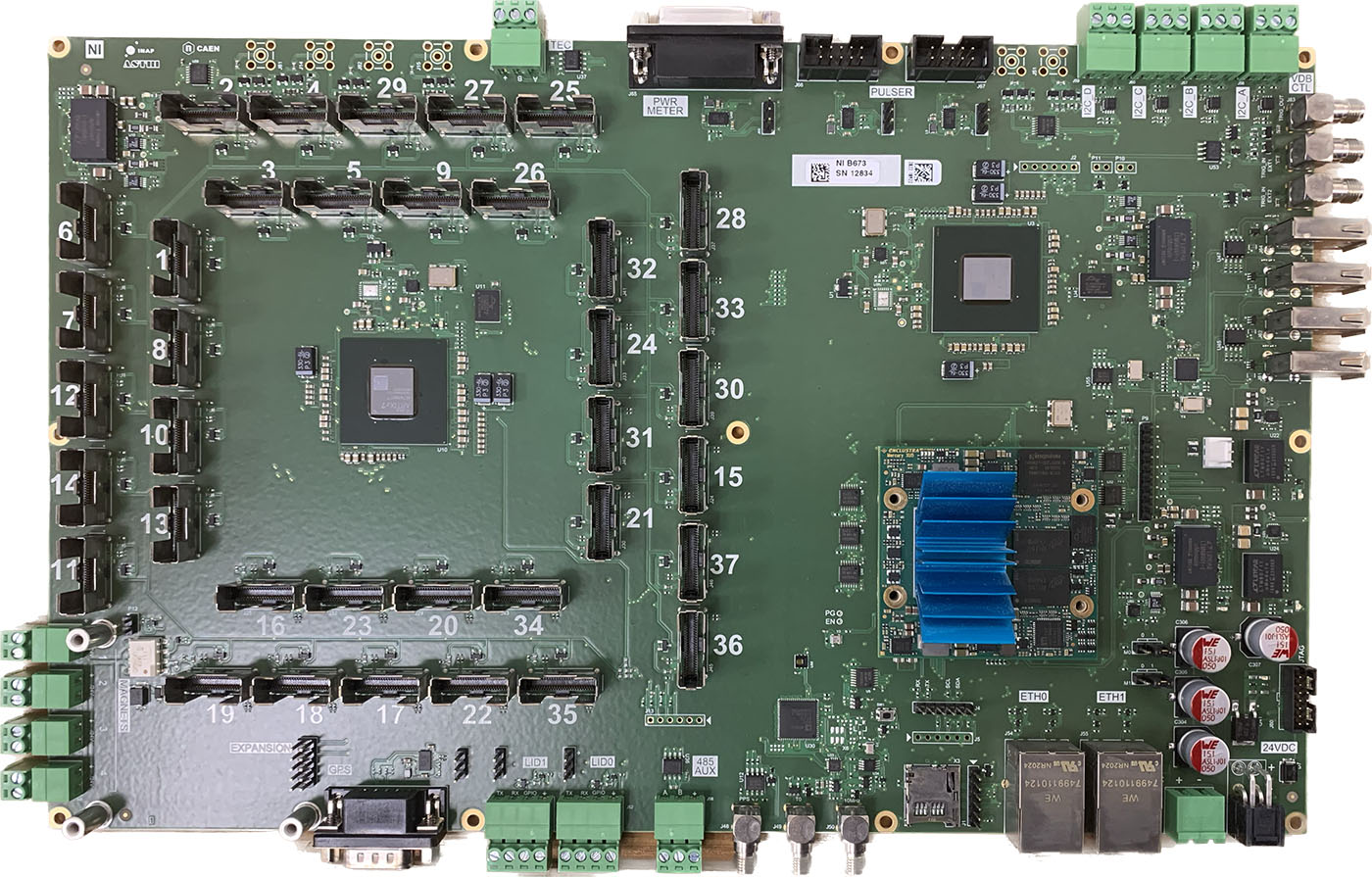
Photograph of the ASTRI Back-End Electronics (BEE) board, showing connectors to all 37 PDMs, dual Artix-7 FPGAs, and the central Zynq UltraScale+ MPSoC.
Photograph of the ASTRI Back-End Electronics (BEE) board, showing connectors to all 37 PDMs, dual Artix-7 FPGAs, and the central Zynq UltraScale+ MPSoC.
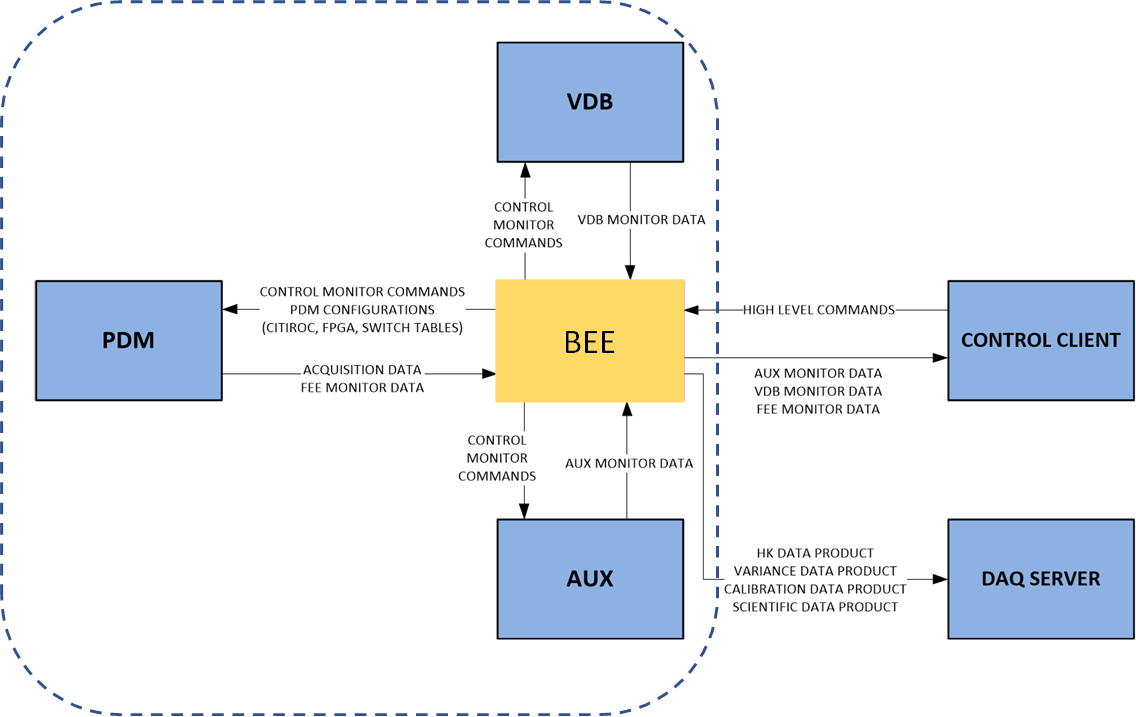
Schematic diagram of the ASTRI camera architecture, illustrating the BEE’s central role in coordinating data and control flow with the PDMs, VDBs, AUX systems, DAQ server, and control client.
Schematic diagram of the ASTRI camera architecture, illustrating the BEE’s central role in coordinating data and control flow with the PDMs, VDBs, AUX systems, DAQ server, and control client.
VDB – Voltage Distribution Boxes
The Voltage Distribution Boxes (VDBs) ensure safe and stable power delivery to the PDMs. Each VDB:
- Supplies temperature-compensated HV (up to 50 V) to the SiPMs, with ripple <1 mV
- Monitors voltage, current, and temperature for all channels
- Provides interlock and alarm mechanisms
- Supports high-brightness conditions, such as full moon or moon-in-FoV
Thanks to their low-noise and high-stability characteristics, VDBs guarantee optimal SiPM operation under variable environmental conditions. They are fully controlled by the BEE via slow control daemons and exposed through the OPC-UA interface.
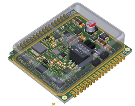
Rendering of a single Voltage Distribution Box (VDB) board used in the ASTRI camera to deliver precise, low-noise power to the front-end electronics and SiPMs.
Rendering of a single Voltage Distribution Box (VDB) board used in the ASTRI camera to deliver precise, low-noise power to the front-end electronics and SiPMs.
High-voltage module of the VDB system, capable of supplying up to 50 V at 100 mA with <1 mV ripple, providing temperature-compensated bias to the SiPM arrays.
High-voltage module of the VDB system, capable of supplying up to 50 V at 100 mA with <1 mV ripple, providing temperature-compensated bias to the SiPM arrays.
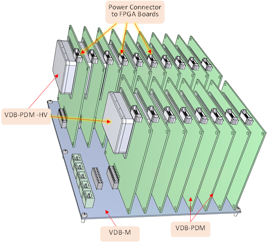
Assembly of 37 VDB units connected to a shared backplane for coordinated power distribution across all Photon Detection Modules in the ASTRI camera.
Assembly of 37 VDB units connected to a shared backplane for coordinated power distribution across all Photon Detection Modules in the ASTRI camera.
Firmware and Real-Time Processing
Both the FEE and BEE incorporate firmware optimized for Cherenkov signal acquisition:
- On the PDM side: real-time triggering, signal digitization, TDC-based timestamping, variance monitoring, and data packaging
- On the BEE side: scientific event reconstruction, timestamp alignment (via White Rabbit), and streaming to the Camera Server
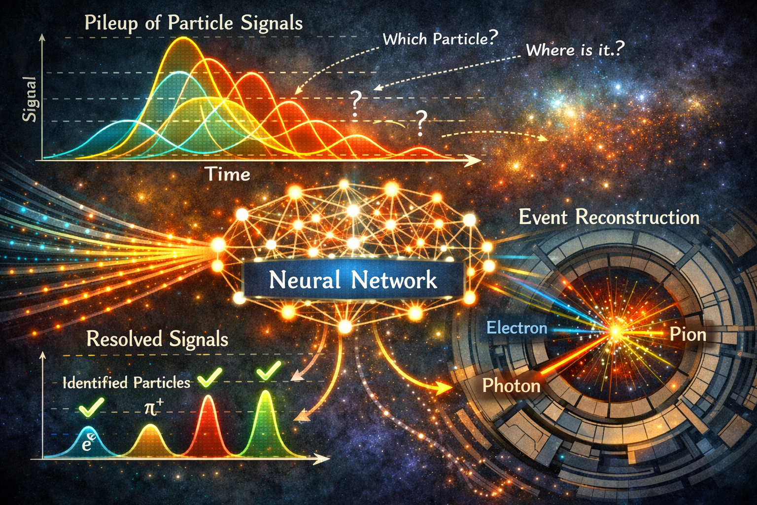
This architecture enables 1 ns time resolution, accurate gain tracking, and robust pile-up mitigation. All firmware modules are designed for deterministic operation under real-time constraints, ensuring high throughput and synchronization across the camera’s 2368 channels.
Complete firmware and software architecture of the camera readout system
Complete firmware and software architecture of the camera readout system